


About a year ago I upgraded my printer from my broken and dust-collecting Monoprice Voxel to a shiny new Creality CR-6 SE, after it was generally available and they had fixed their initial release bugs. The jump in quality was fantastic and mesh bed leveling made the first layer so clean. It didn't take long before I had made a number of additional upgrades to the printer, moved over to OctoPrint and started experimenting with other materials beyond PLA. When I first started with PETG, I was actually able to get away with just making sure the fan in the room was off and I taped some cardboard around the base to keep walking by from disturbing the print. For small things, this worked fine but larger and longer prints still had peeling issues and humidity would cause prints to string or strand. I had known for a while I'd need to get or build an enclosure so this was enough impetus for me to do it. I had also known that I should be protecting myself from VOCs and microscopic plastic particles from the printing process, so I wanted my enclosure to have enough space for expansion inside.
Before starting, however, I wanted a concrete set of goals that this would accomplish. Here's what I came up with:
- Allow for higher ambient temperatures. No need for active heating, as the bed and tool heating should be sufficient
- A modicum of fire safety, likely meaning a foil lining
- Fully enclosed with only wires going in and out, which meant room for the spool as well
- Good lighting so I didn't have to keep the ceiling lights on in order to get a good time-lapse
- Large doors on the front that offer good visibility and access to the printer and filament without having to disassemble anything
- Some form of air filtering that can actively cycle the air
Overall, I was able to accomplish these and more. As this project has been ongoing for several months and I have been remiss in writing a build log as I go, this post will act more as a show and tell and a retrospective.
Construction
After looking into things like the IKEA Lack-based enclosures and being in the middle of the pandemic where lucite was at an absolute premium, I opted instead to build using 2020 extrusion and thin plywood as both were available and reasonably priced, and I could custom cut everything to exactly the size that I wanted.
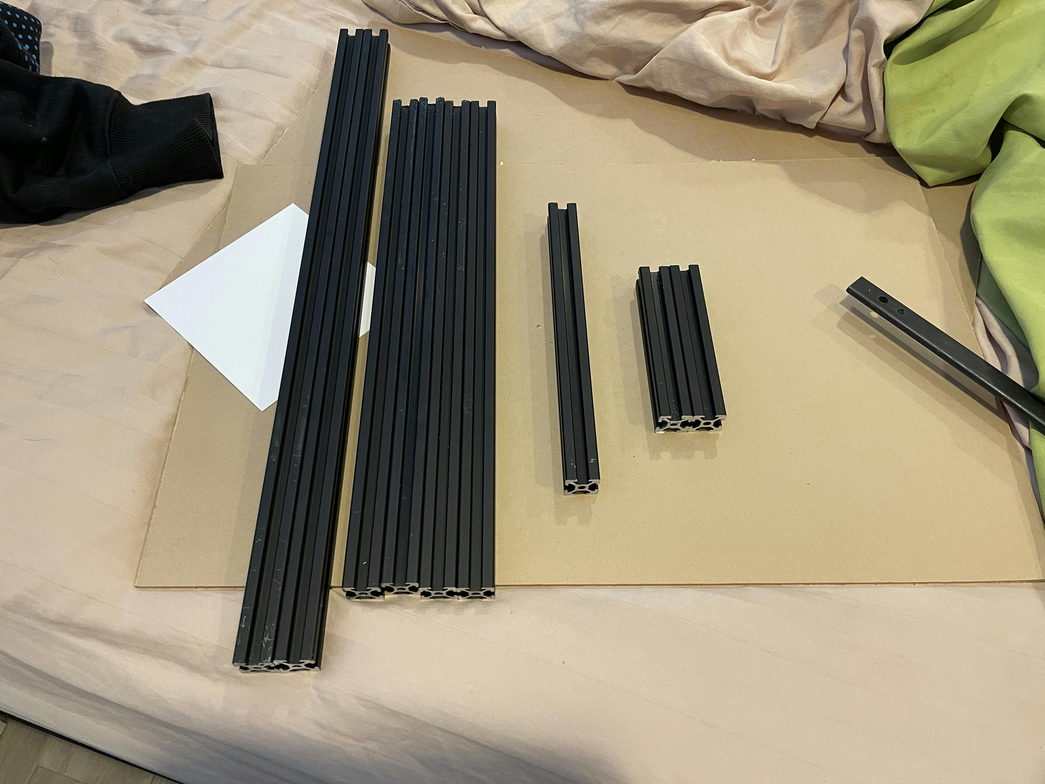 Fig 1. Cutting and collecting all the frame rods.
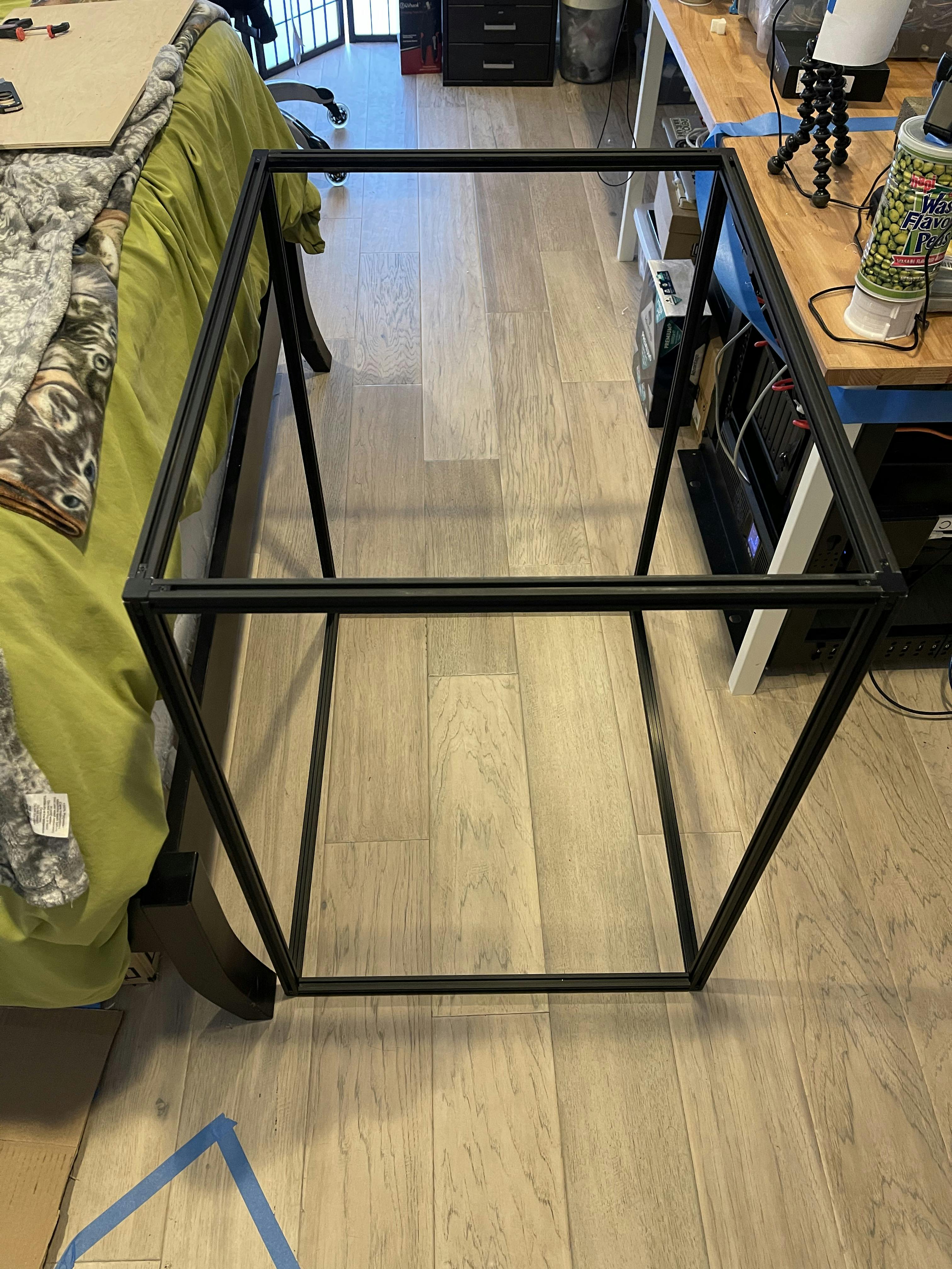 Fig 2. Initial assembly of the frame and checking my measurements.
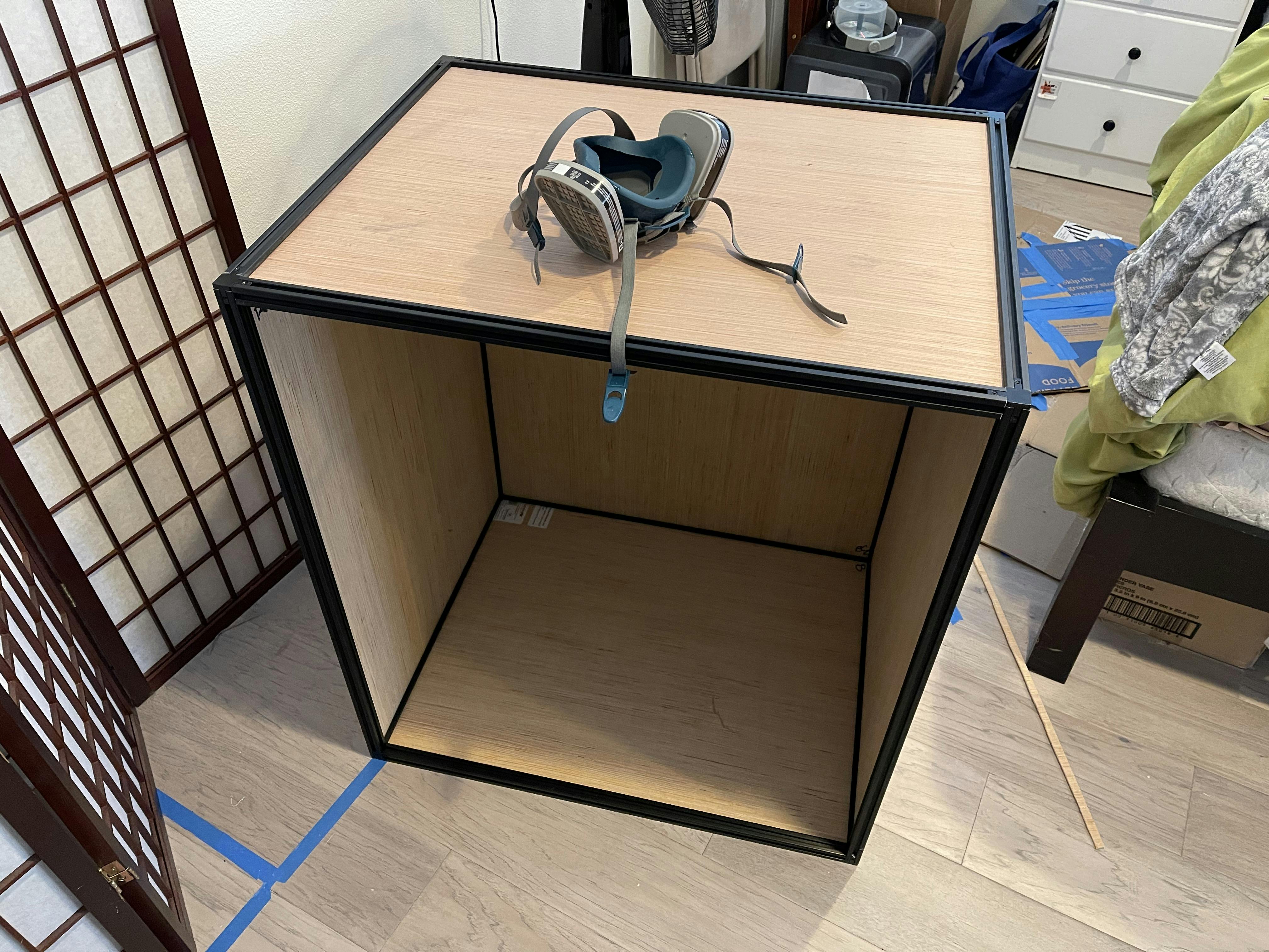 Fig 3. Some hiccups with fitment but nothing a hacksaw and some sanding can't fix.
As with any project where planning only goes so far and you have to make it up as you go, I managed to mis-calculate the walls of the box, and instead of cutting two sides, a top, back and having scraps for the front frame where the door would go, I cut a full front and had to piece together the side from scraps. Luckily, I have enough material and I was able to tape it together with the same interior aluminum tape.
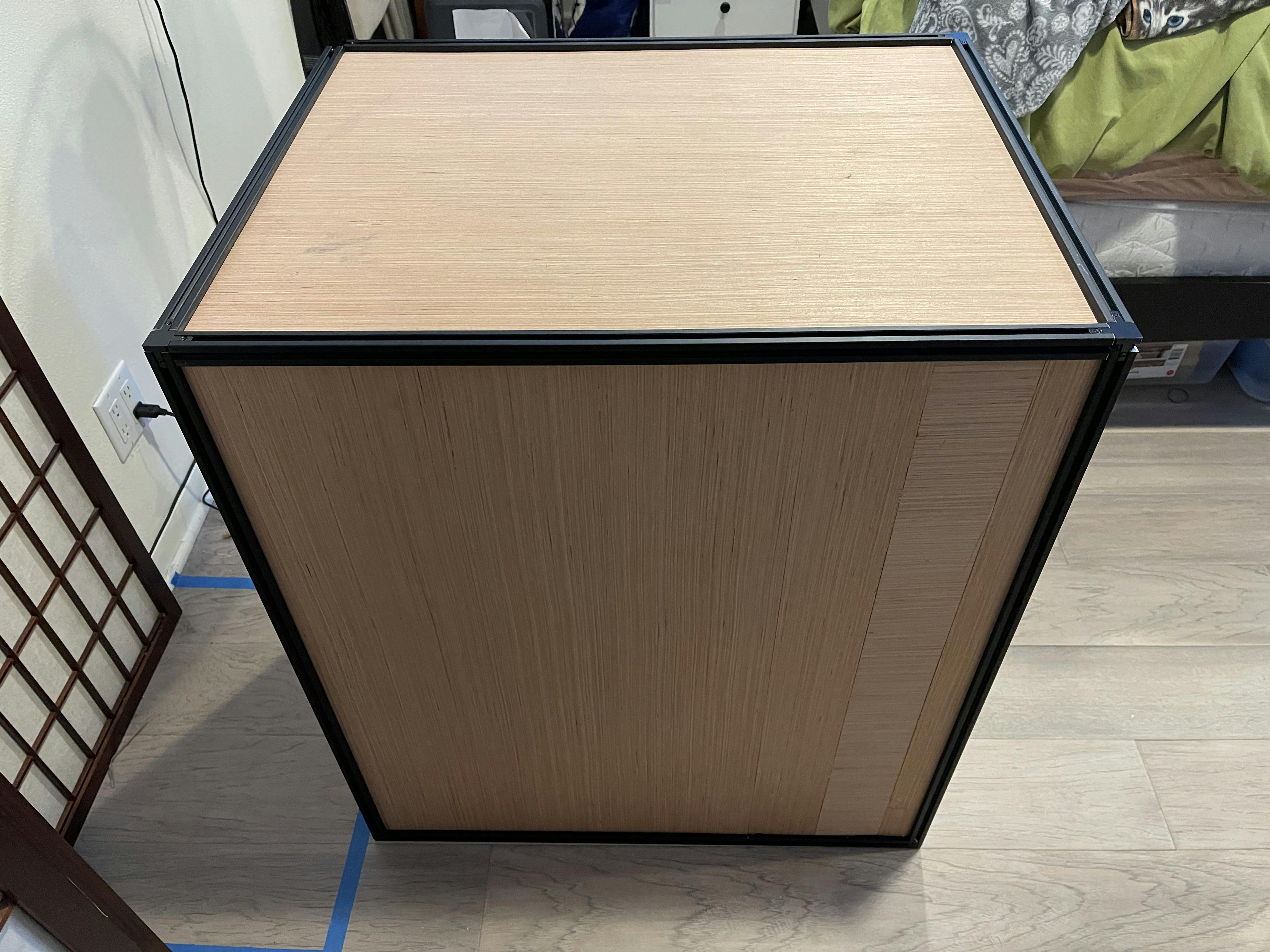 Fig 4. When in doubt, patchwork it together and hold it with aluminum tape.
With everything looking good, I felt confident starting on the lighting at the top. Up until this point, I had been using film lights to light up the print bed while taking time-lapses and I wanted something integrated into the enclosure to be better for both time-lapses and just keeping an eye on the prints. So, when it comes to lighting, the first thing I go to is, of course, addressable LEDs. Specifically, I wanted a good white light so I went with RGBW strips. Here's the first test with an Adafruit Arduino-compatible board on a breadboard:
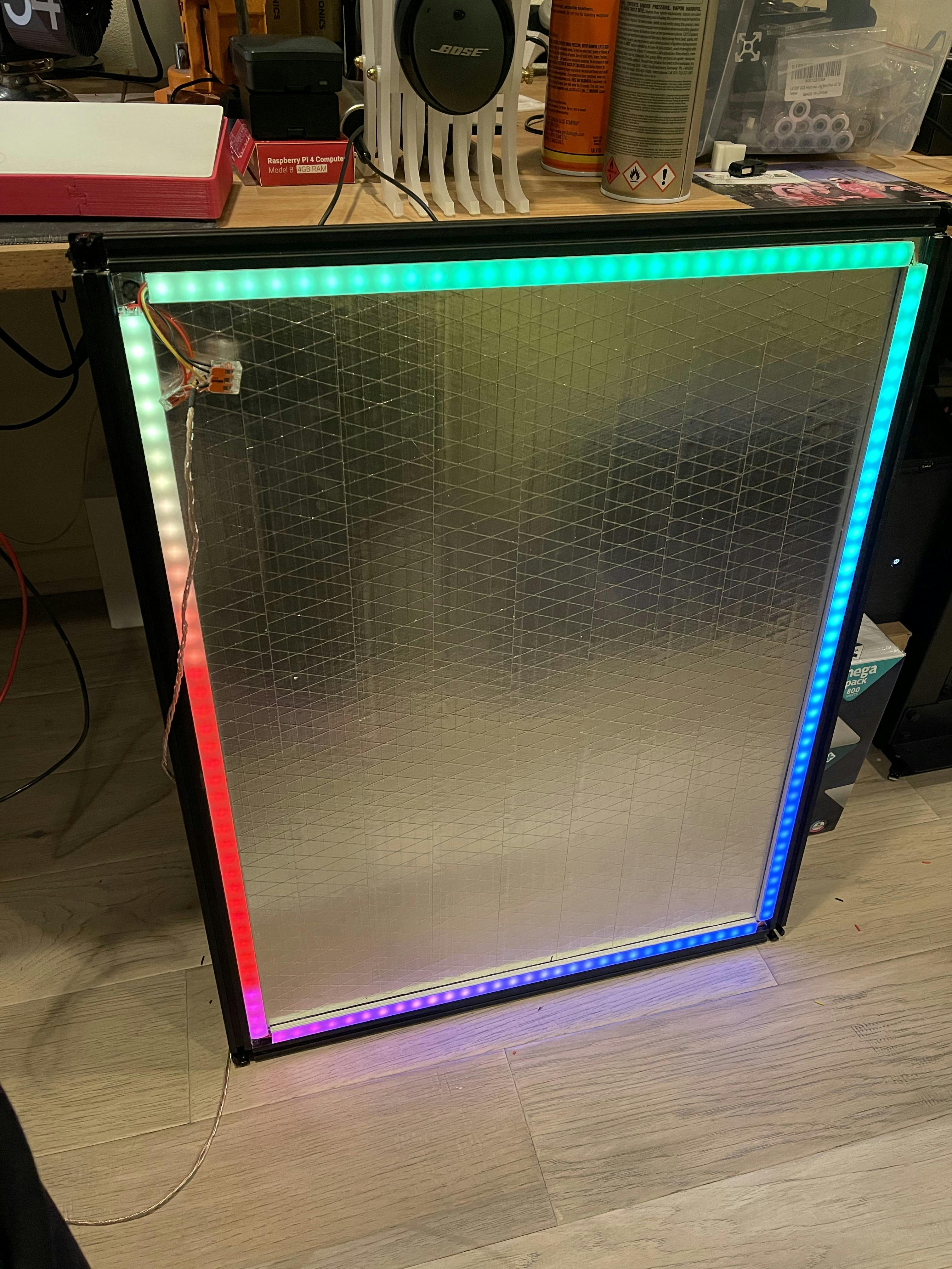 Fig 5. Initial testing of lighting, checking solder, power distribution and diffuser rail.
With the lighting looking good, it was time to start buttoning it all up. Final fit checks, and foil checks were good, so I tightened it all and put it up on my desk. And... phew that was a close call for size. I somehow managed to forget to check it up to this point and I feel very lucky that it all fits as well as it does.
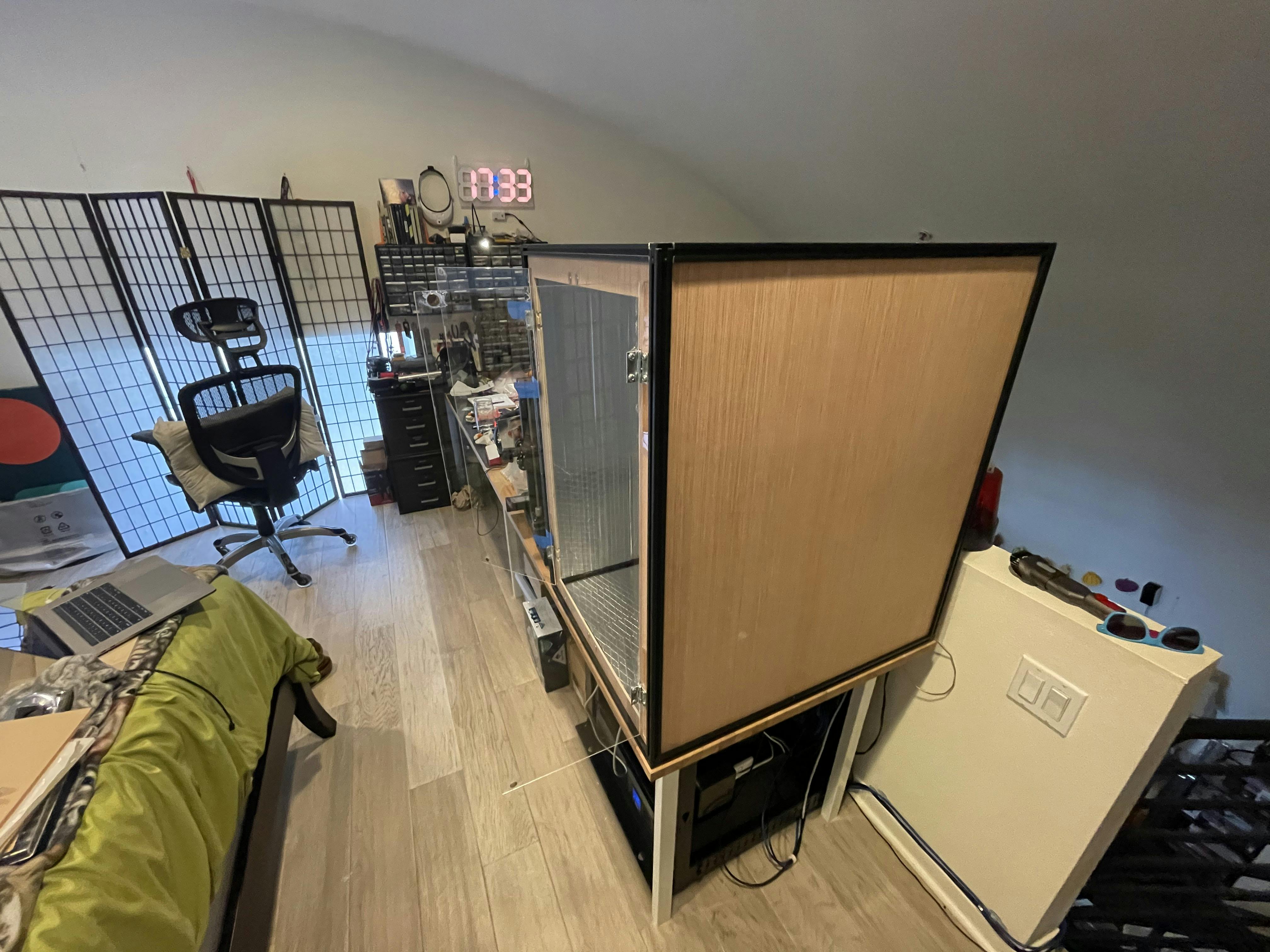 Fig 6. Super Pro... by sheer chance. Look at that fit!
And finally, jumping ahead a bit, here is a temperature and humidity monitor in there while running a hot PETG print. Lookin' good!!
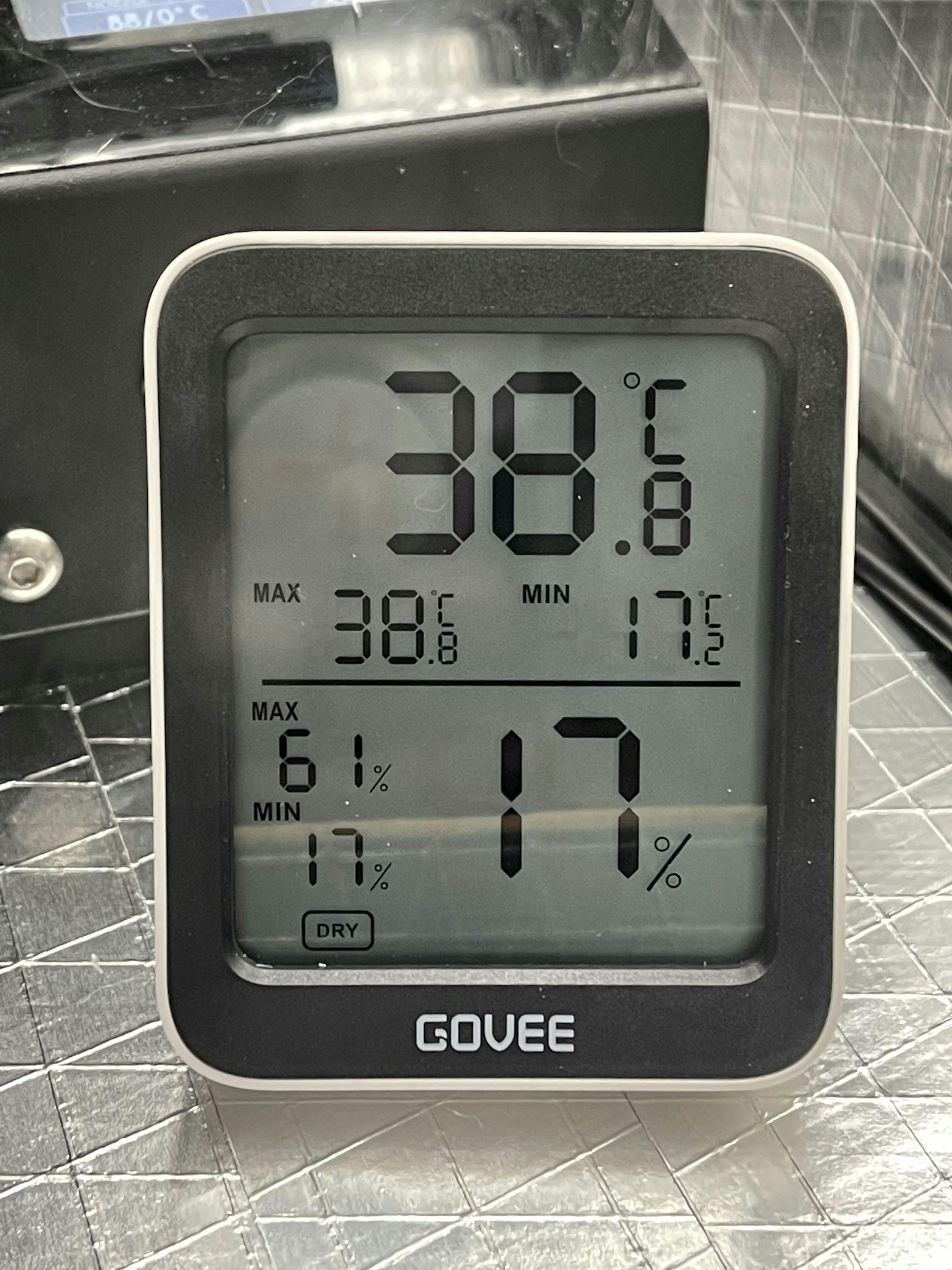 Fig 7. Not bad, not bad at all.
In the next installment, I'll go into how I scrap the original lighting idea, get a new lighting setup running, then how I and get everything into its final form. See you then!